You may feel that creating a keyboard means manufacture different pieces, aseembly them altoghether and start playing around but, have you ever thought how do we test every component? We do it, in fact, with great care.
If you are in the keebs world you will be aware that one of our main "characters" here are our PCBAs but, how do we test them? Don't go anywhere because you are going to learn what the Jig test is and why we use it. Let's go!
All about PCBAs
PCBA's can be complicated;If we take a look at the PCBA of the Raise 2 keyboard, it's made of all these different components that are soldered onto the board: sockets for the keyboard switches, the LEDs for the backlight, the microcontroller, and all of these tiny wires that connect all the components together.
Just for those who don't know the difference between a PCB and PCBA, a PCB is the blank circuit board with no electronic components attached, while a PCBA is a completed assembly that contains all of the components needed.

To ensure that the PCBA’s work, all functionality and interfaces must be tested.If we find something that doesn't work, we'd know which part of the assembly made this error and we can fix it and prevent it from happening again.
Time is of the essence; the sooner we check the electronics, the sooner we can assemble the keyboards and ship them to you. That's what that the devices we show you at the beginning of the video (you have it above) are for.
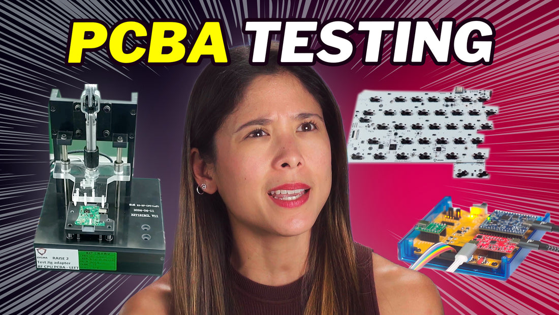
The Test Jig
As an example, here's the setup that we have implemented in our PCBA factory in China to test the PCBAs of the Raise 2 keyboard.

Here we have a test jig, which is an adapter for the PCBA we want to test.

The jig contains a lot of test pins which connect exactly to test points on the PCBA.

Those test points then connect to an interface tester box which runs a special firmware and is then connected to a computer, running a Python test script. If there is anything failing, we see a red text on the computer screen, meaning repairment is needed.
This test is used to program the bootloader, flash the firmware, and check each and every functionality of the PCBA such as:
- The power regulator
- The USB flash memory access
- The I2C and SPI interface to the Neuron
- CC1 and CC2 input lines
- RGBW BackLight LED MATRIX
- UG drive interface
- Module Interface
- "RESET" and "BOOTLOADER" push button lines
We also test the connectors of the USBC cable for both sides and continue with the tests. What you've seen is just one of the test jigs for the keyscanner PCBA of the Raise 2 keyboard. It's the biggest test jig we have but it's not the only one.
How many Jig test we do?
As you may or may not know, the Raise 2 keyboard has 7 PCBAs: 2 for the keyscanner - one on each side, 2 for the underglow - one on each side, 2 for the RF gateway - again, one on each side, and 1 for the Neuron. Which means... 7 test jigs.
Maybe you are asking yourself": Hey, Dygma, how do you test the neuron?" (and if not, sorry mate, we are going to explain it anyway).

Inside this jig, there's a programming interface that allows us to flash the data on the Neuron's microcontroller. It then has a functional test but we don't use the jig for that. It's simply connected to the tester box using USBC cables. Since this is done by human interaction, it is the most time-consuming functional test.
The test jig for the underglow PCB is the simplest. It doesn't need a computer, but just the tester box that sends all the needed commands to measure the power consumption of each LED and then tests each and every one of them.

And the last jig is for the RF PCBA, which is the most complicated test, because we'd need to test the battery charging, battery monitoring, the communication over wires, and the communication over wireless. Besides the jig, computer, and interface tester, it has its own programming board.

To test the battery charger functionality without actually using a keyboard, we simulate the keyboard consumption by using two LEDs assembled in the interface tester box, that draws more or less the same amount of current that a keyboard would draw.
A very demanding process
We've only really just shared with you the surface level of what goes on in the testing phase of the electronics. The team have gone through great lengths in making the different test setups for all the PCBAs of our keyboards.

All these PCBAs are required so the keyboards can work wirelessly, via RF and bluetooth, and wired. You can also check out this video if you want to know how we made it happen. It was no easy task.
What do you think about this? Did you know anything about jig tests before reading this bible we made to explain?
As always, if you have any questions, feel free to ask us on Reddit or Discord.